 |


| Quantity: | |
|---|---|
1"-6" ROLL GROOVING MACHINE (TWG-VA-R)
TWG-VA-R is one roll grooving machine for small pipe from 1inch to 6inch, it is a small and light machine with simple design of carriage, which is convenient and easy to be moved by workers.
OPERATION AND ADJUSTMENT.
1. Before first grooving
Test drive the machine always before the first grooving to check that everything seems normal. When servicing, setting groove depth or changing pinch rollers or knurl shafts the machine should always be switched off.
")
2. Preparing the pipe
Pipes are square cut. After cutting it is important to make sure that pipe end is free from burrs, dirt and oil. Control especially the area from the pipe end to the groove end. Chamfer must not exceed 1.5 mm. With hot-dip galvanized and powder coated pipes ensure that no flaking occurs on the gasket seating surface. If so, the entire surface is sanded clean and afterwards treated with anti-rust paint for powder-coated pipes and zinc paint for galvanized pipes. Note that powder-coated pipes have plastic coating which may crack when machining is performed. We recommend that the surface is first sanded, then grooved and treated with anti-rust paint.
3. Placing the pipe
Place the end of the pipe on the knurl shaft of the machine and the other end on the pipe support. Pipe support
should be placed on ¾ of the total pipe length from the grooving machine. Target support for the pipe so that the pipe is aligned towards the machine. Turn height adjustment handle on the pipe support so that the pipe is horizontally level or slopes 1-2 degrees towards the pipe support.
")
4. Adjusting groove depth
Test grooving should always be performed after setting groove depth and after changing pipe size. Tighten the relief valve, shake the oil pump handle, make the upper roller downward and touch the pipe surface. Then stop it. Turn the limit nut down, let it contact the oil pump surface, check the groove depth on the form, if 3inch pipe, the groove depth is 1.98mm, starting from the red line, rotate the limit nut 1.98mm up, then turn the fastening nut down unit it touch the limit nut, fix it. (one rotation of limit nut equals 2.5mm)
5. Grooving and groove standard

Pipe size (inch) | O.D | A±0.5 | B±0.5 | D±0.5 | C | Flare | |
Max.(mm) | Min.(mm) | ||||||
1” | 33.7 | 15.88 | 7.14 | 1.65 | 30.23 | 29.85 | 36.3 |
1 1/4” | 42.4 | 15.88 | 7.14 | 1.65 | 38.99 | 38.61 | 45 |
1 1/2” | 48.3 | 15.88 | 7.14 | 1.65 | 45.09 | 44.70 | 51.1 |
2” | 60.3 | 15.88 | 8.74 | 1.65 | 57.15 | 56.77 | 63 |
2-1/2” | 76.1 | 15.88 | 8.74 | 1.98 | 72.26 | 71.80 | 75.7 |
3” | 88.9 | 15.88 | 8.74 | 1.98 | 84.94 | 84.48 | 78.7 |
4” | 108.0 | 15.88 | 8.74 | 2.11 | 103.73 | 103.22 | 91.4 |
4” | 114.3 | 15.88 | 8.74 | 2.11 | 110.08 | 109.57 | 110.5 |
5” | 133.0 | 15.88 | 8.74 | 2.11 | 129.13 | 128.62 | 135.9 |
5” | 139.7 | 15.88 | 8.74 | 2.11 | 135.48 | 134.97 | 142.2 |
6” | 159.0 | 15.88 | 8.74 | 2.16 | 153.21 | 152.45 | 161.3 |
6” | 165.1 | 15.88 | 8.74 | 2.16 | 160.78 | 160.22 | 167.6 |
6” | 168.3 | 15.88 | 8.74 | 2.16 | 163.96 | 163.40 | 170.9 |
"A" Dimension – The "A" dimension, or the distance from the pipe end to the groove, identifies the gasket seating area. This area must be free from indentations, projections (including weld seams), and roll marks from the pipe end to the groove to ensure a leak-tight seal. All foreign material, such as loose paint, scale, oil, grease, chips, rust, and dirt must be removed.
"B" Dimension – The "B" dimension, or groove width, controls expansion, contraction, and angular deflection of flexible couplings by the distance it is located from the pipe and its width in relation to the coupling housings’ "key" width. The bottom of the groove must be free of all foreign material, such as dirt, chips, rust, and scale that may interfere with proper coupling assembly.
"C" Dimension – The "C" dimension is the average diameter at the base of the groove. This dimension must be within the diameter’s tolerance and concentric with the OD for proper coupling fit. The groove must be of uniform depth for the entire pipe circumference.
"D" Dimension – The "D" dimension is the normal depth of the groove and is a reference for a "trial groove" only. Variations in pipe OD affect this dimension and must be altered, if necessary, to keep the "C" dimension within tolerance. The groove diameter must conform to the "C" dimension described above.
"F" Dimension – Maximum allowable pipe-end flare diameter is measured at the extreme pipe-end diameter.
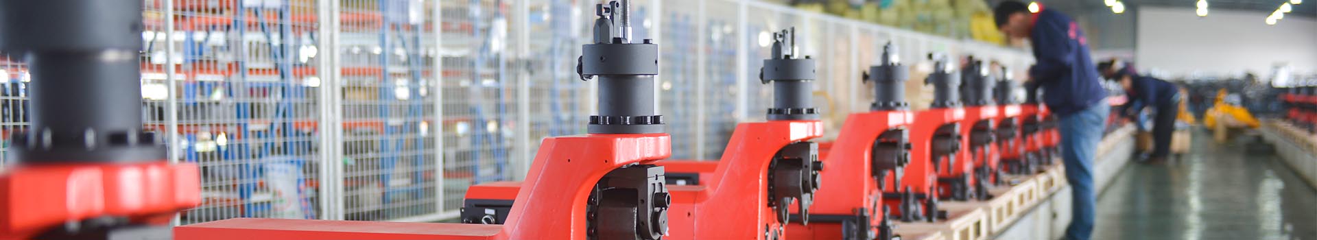
After ten years’ development, Tuwei have series roll grooving machines. Anyway, Tuwei will be committed to developing better machines to meet different needs in the future.
PRODUCT DETAILS